Router Microarchitecture
The router is where the NoC architecture stops being a collection of ideas and starts becoming actual hardware.
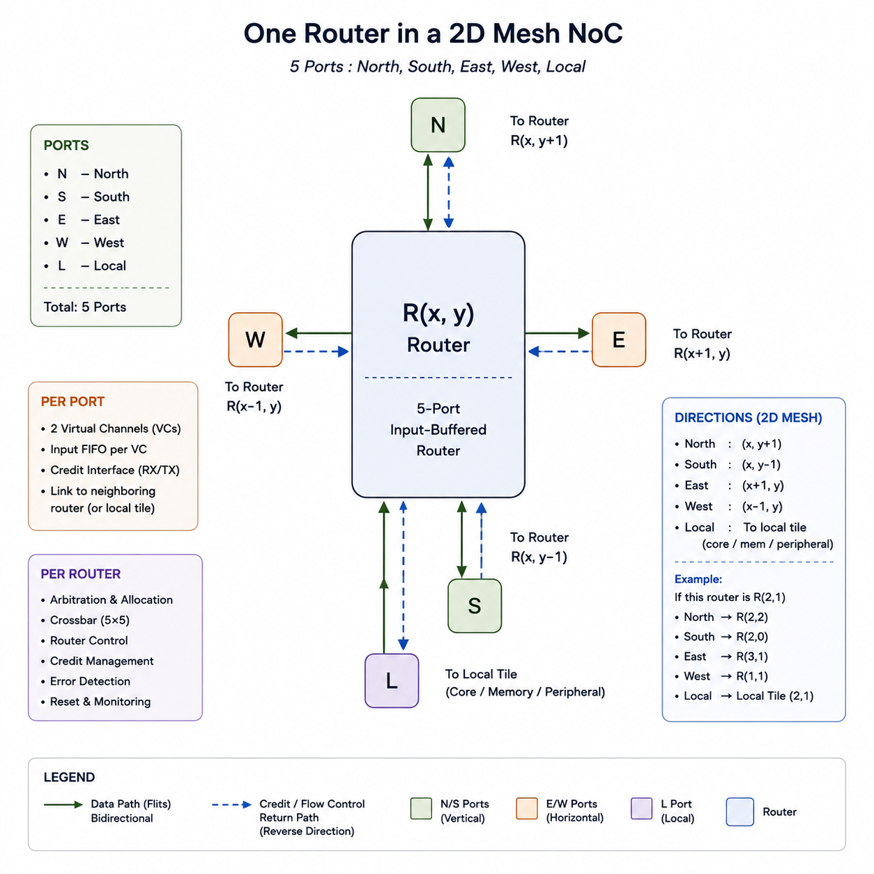
Five-port router in the 2D mesh. .
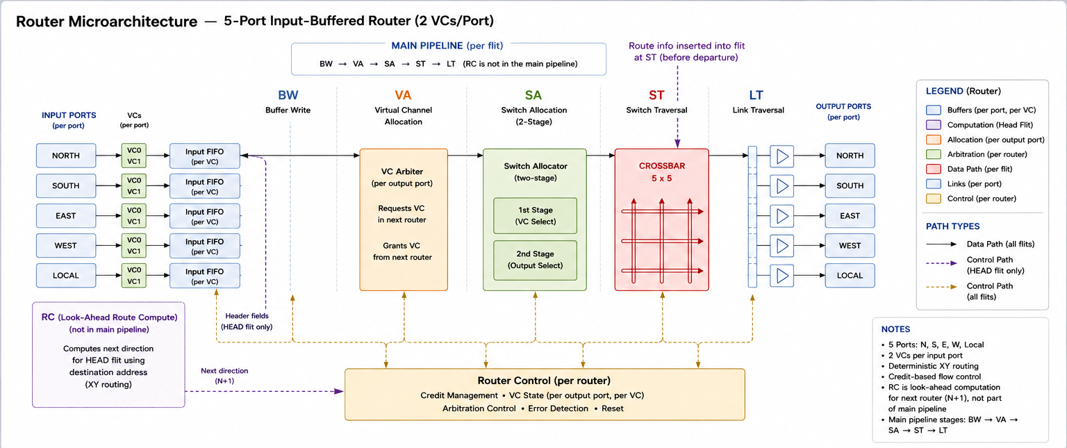
Router microarchitecture.
Its job is deceptively simple: accept a flit, figure out where it needs to go, acquire the resources required to get there, resolve contention, and move it to the next router.
The difficulty is that all of those things are competing for the same few cycles.
The current router uses a 5-port input-buffered architecture with two virtual channels per port, credit-based flow control, deterministic XY routing, and a pipelined datapath:
BW → VA → SA → ST → LT
The stages are arranged so that work which can be done early is done early, while the stages responsible for actually moving data are kept as clean as possible.
Starting with the Buffer
The first architectural question was where to put the buffers.
Input buffering is the obvious answer only until you stop and ask why.
A flit arrives at an input port, but it may not be able to move immediately. The router may be busy, the required downstream VC may not be available, or the flit may lose switch arbitration. Something has to hold it while that gets sorted out.
With input buffering, that waiting happens exactly where the flit arrived.
The flit sits in the input FIFO until it has everything it needs to move. The input side does not need to know whether the crossbar is available or whether the flit will win arbitration. It just needs to accept the transfer when it has buffer space.
That makes the input buffer a useful boundary between receiving traffic and deciding what to do with it.
Why not output buffering?
The alternative initially seems reasonable.
Suppose North and West both want East in the same cycle. Only one flit can physically leave through East, so one of them has to wait somewhere. An output buffer seems like a natural place to absorb that contention. It appears to free up the input side and let incoming traffic continue while the output handles the waiting.
My first assumption was that this would then require another arbitration stage at the output to decide which waiting flit should be served next.
Then I looked at the router pipeline again.
SA has already made that decision.
Switch allocation has already decided which input gets access to a given output for the current cycle. The crossbar is not making another scheduling decision. It is simply implementing the connection selected by the allocator.
So an additional output arbiter would just be making the same decision twice.
That still leaves the more fundamental question: what happens if the input buffers disappear entirely and only the output side is buffered?
Now the crossbar has to accept traffic from every input as it arrives, with nothing upstream holding a flit while the router decides whether it can proceed.
There are two obvious ways to make that work.
The first is to run the crossbar faster than the rest of the router so it can drain all possible incoming transfers within a single router cycle.
No.
The second is to buffer at the crosspoints of the crossbar. For an (N)-port router, that potentially means (N^2) buffering locations.
Five ports is not catastrophic. The problem is the direction of the scaling. The buffering requirement grows quadratically with the number of ports.
Multi-write-port FIFOs can change the implementation tradeoff, but introducing more complicated memory structures simply to avoid buffering at the inputs is difficult to justify.
Input buffering therefore remains the architectural choice.
Not because it was the first option considered, but because the alternatives were followed far enough to expose their actual costs.
The Flit Lifecycle
With the buffering decision made, the next question is what actually happens to a flit once it enters the router.
At a high level:
Buffer → Allocate VC → Allocate Switch → Traverse Crossbar → Traverse Link
The actual pipeline is:
BW → VA → SA → ST → LT
Each stage has a fairly specific job.
BW: Buffer Write
A flit arrives at an input port.
The first thing that happens is, thankfully, not routing.
The incoming transfer is sampled on the clock edge and the flit is written into the input FIFO. This stage is deliberately simple. No routing, no arbitration, no credit management.
Just:
Is the transfer valid? If it is, write the flit.
I want the rest of the router to work with registered state rather than whatever happens to be sitting on the input wires. There is no point doing interesting work before the data has even been captured.
Once the flit is in the input buffer, the router can start working on it.
Route Computation
If the flit is a head flit, route computation begins.
The slightly strange part is that the router is calculating the route for the next router, not this one.
This router already knows where the flit is. What matters is where it needs to go after it leaves.
The destination information is extracted from the header and used to determine the next direction. Since the network uses deterministic XY routing, the decision is straightforward, but the important part is when it happens.
The route is computed early rather than becoming another piece of work on the critical path when the flit is finally ready to cross the switch.
The result can sit there while the flit waits for the resources it needs.
Might as well make the waiting time useful.
VA: Virtual Channel Allocation
The head flit now needs a VC in the next router.
Body and tail flits do not need to repeat this process. They follow the VC established by their head flit.
The mesh topology gives us a useful shortcut here.
If a flit needs to enter the West port of the next router, it has to leave the current router through its East output. The same relationship exists for every direction. The current output directly corresponds to the input port that the flit will use at the next router.
That means the VC request can be handled using the VC arbiter associated with the current output port.
If multiple input ports want VCs at the same downstream port, they are already competing at the same output here. The VC arbiter resolves that contention and grants one of the available downstream VCs.
This is where VA and SA need to be kept separate.
VA is asking:
“Can I reserve a VC at the next router?”
SA is asking:
“Can I use this router’s crossbar?”
Two different resources, two different decisions.
Winning VC allocation means the flit has secured a place in the next router.
It still hasn’t earned the right to leave this one.
SA: Switch Allocation
Now the flit reaches switch allocation.
There are two rounds because there are two different contention problems.
First stage
An input port can have multiple VCs with eligible flits.
Only one of them can be presented to the crossbar in a cycle, so the first stage chooses which VC gets to compete.
Now every input has at most one contender.
Second stage
The remaining contenders compete for the output ports they want.
North and West might both want East this cycle.
East is, unfortunately, still only one East.
The second stage resolves that contention and selects which input gets the output.
Nothing has moved yet.
VA and SA are making decisions. The flit is still sitting in the input FIFO.
If it loses arbitration, it stays there and tries again on the next cycle.
There is no partial credit for almost winning.
ST: Switch Traversal
Once the flit wins switch allocation, the router finally gets to move some data.
The crossbar establishes the connection selected by the allocator, and the flit traverses the crossbar to its granted output.
This is where all the earlier decisions become an actual data movement.
The route information computed earlier is also inserted into the flit’s payload at this point.
Until now, the route computation was local control information. Now it becomes part of the flit itself and travels with it to the next router.
The router has done its thinking.
The flit gets to leave.
LT: Link Traversal
The flit then traverses the physical link to the next router.
This is probably the least intellectually exciting stage. After all the allocation and arbitration, it is essentially:
send the flit.
But the work done in the previous stages matters here.
When the flit arrives at the next router, the route information carried in its payload is already available. The next router does not need to spend another cycle figuring out the direction from scratch.
It can use the information computed by the previous router and continue the same process.
Then the cycle repeats.
Virtual Channels and Flow Control
The router has two virtual channels per port, with credit-based flow control between neighboring routers.
The important distinction is that a virtual channel is not another physical link. Multiple logical channels share the same physical resources while maintaining separate flow-control state.
The credits provide the information needed to determine whether the downstream buffer has space before sending a flit.
This fits naturally with the input-buffered architecture. The downstream router owns the storage, while the upstream router keeps track of whether that storage can accept another flit.
The resulting relationship is simple:
Downstream buffer space → credit → upstream transmission permission
The details of the credit state and per-VC control form part of the input-port architecture rather than being mixed into the data path itself.
The Crossbar
The crossbar is the physical structure that connects the router’s inputs to its outputs.
It does not decide which input should win.
That decision has already been made by switch allocation.
This distinction matters because it keeps the control and datapath separate. SA produces the connections that are allowed for the current cycle, and the crossbar implements those connections.
The result is a clean division:
Allocator: decide.
Crossbar: connect.
The crossbar therefore does not need to understand packet destinations, VC ownership, or arbitration policy. It only needs to establish the selected input-to-output paths and move the corresponding flits.
Putting the Router Together
At this point the router can be viewed as a sequence of increasingly constrained decisions.
A flit first becomes local state.
BW
Then its destination is determined and, for a head flit, a downstream VC is requested.
VA
Once the required resources are available, it competes for the crossbar.
SA
If it wins, the datapath finally moves it.
ST
Then the physical link carries it to the next router.
LT
The entire path is therefore:
              ┌───────────────┐
              │  Input FIFO   │
              └───────┬───────┘
                      │
                      ▼
                     BW
                      │
                      ▼
                     VA
                      │
                      ▼
                     SA
                      │
                      ▼
                  Crossbar
                      │
                      ▼
                     ST
                      │
                      ▼
                     LT
                      │
                      ▼
                Next Router
The architecture is intentionally structured so that eligibility, allocation, and movement are separate problems.
A flit can be present without being eligible.
It can be eligible without winning arbitration.
It can win arbitration without having physically moved yet.
Only after all of those conditions are satisfied does the crossbar actually carry the data.
That separation is what allows the router to pipeline the work rather than making every stage wait for the entire decision process to finish.
What Comes Next
The microarchitecture is now defined well enough that the next problem is no longer deciding what the router should be.
It is building it.
The immediate work is around the individual structures that make up this pipeline: the input-port cluster, VC control, arbitration, crossbar, and the ST/LT datapath.
Once those pieces are implemented and verified independently, they can be brought together into the complete router.
At that point the interesting question changes from:
“Can this router move a flit?”
to:
“What happens when an entire network of these routers starts moving them at the same time?”
That is where contention stops being a local issue and becomes a network-wide behavior.